This section describes how to establish an LU 6.2 connection using
IBM Communications Server for Windows NT, Version 5.0. You may
use any of the supported LU 6.2 products for this platform. The
panels of other products will not be identical to those shown here, but most
of their content will be similar.
To configure the local node, follow these steps:
- From the Scenarios pull-down of the Communications Server SNA
Node Configuration window, select the CPI-C, APPC or 5250 Emulation
scenario.
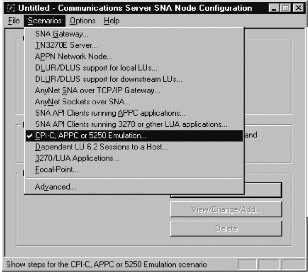
The CPI-C, APPC or 5250 Emulation scenario window is displayed.
- Click on Configure Node, then click on New.
The Define the Node property sheet is displayed.
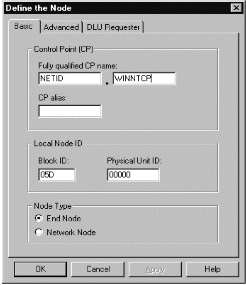
- In the Fully qualified CP name field on the Basic page, enter
the unique ID of the network to which you are connected ((2)) and the
control point name ((3)). Click on OK to
continue.
- From the SNA Node Configuration window, click on Configure Local LU
6.2, then click on New. The Define a Local LU
6.2 window is displayed.
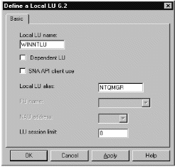
- In the Local LU name field on the Basic page, enter the name of
the LU on your workstation ((5)). In the Local LU
alias field, enter the name by which your local LU will be known to your
applications ((6)). Click on OK to continue.
To add a connection, follow these steps:
- From the SNA Node Configuration window, select Configure
Devices, select LAN as the DLC type, then click on
New. The Define a LAN Device property sheet is
displayed.
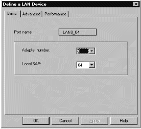
- If you have the LLC2 protocol installed with Communications Server for
Windows NT, the Adapter number list box lists the available LAN
adapters. See the help file INLLC40.HLP (Windows NT 4.0)
or INLLC35.HLP (Windows NT 3.51) in the Communications Server
installation directory for LLC2 installation instructions.
- The default values displayed on the Define a LAN Device Basic page may be
accepted. Click on OK to continue.
- From the SNA Node Configuration window, select Configure
Connections, select LAN as the DLC type, then click on
New. The Define a LAN Connection property sheet is
displayed.
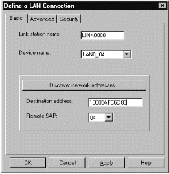
- In the Destination address field on the Basic page, enter the
LAN address of the system to which you are connecting ((11)).
Select the Advanced page.
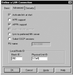
- In the Block ID field on the Advanced page, enter the local
node ID (hex) ((4)). Select the Security page.
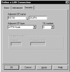
- In the Adjacent CP name field on the Security page, enter the
network name and control point name of the remote node ((12) and
(13)). In the Adjacent CP type field, enter APPN
Node. You do not need to complete the Adjacent node ID
field for a peer-to-peer connection. Click on OK to
continue. Take note of the default link name used to identify this new
definition (for example, LINK0000).
To add a partner LU definition, follow these steps:
- From the SNA Node Configuration window, select Configure Partner LU
6.2, then click on New. The Define a Partner LU
6.2 property sheet is displayed.
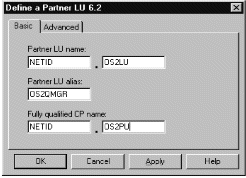
- In the Partner LU name field on the Basic page, enter the
network name ((12)) and LU name of the remote system
((16)). In the Partner LU alias field, enter the
remote LU alias ((15)). In the Fully qualified CP
name fields, enter the network name and control point name of the remote
system ((12) and (13)). Click on OK to
continue.
To add a CPI-C Side information entry, follow these steps:
- From the SNA Node Configuration window, select Configure CPI-C Side
Information, then click on New. The Define a CPI-C
Side Information property sheet is displayed.
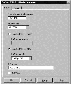
- In the Symbolic destination name field of the Basic page, enter
the CPI-C name ((18)). In the Mode name field, enter
the mode value ((17)). Enter either a fully qualified
partner LU name ((12).(16)) or a partner LU
alias ((15)) depending on what you choose in the CPI-C Side
Information property sheet. In the TP name field, enter the
partner TP name ((19)). Click on OK to
continue.
To add a Transaction Program (TP) definition, follow these steps:
- From the SNA Node Configuration window, select Configure Transaction
Programs, then click on New. The Define a Transaction
Program property sheet is displayed.
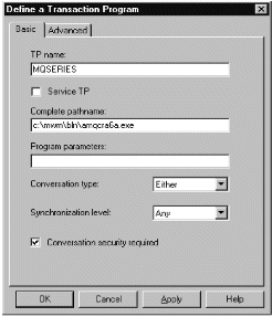
- In the TP name field on the Basic page, enter the transaction
program name ((7)). In the Complete pathname field,
enter the actual path and name of the the program that will be run when a
conversation is initiated with your workstation ((8)). When you
are happy with the settings, click on OK to continue.
- In order to be able to stop the WebSphere MQ Transaction Program, you need
to start it in one of the following ways:
- Check Service TP on the Basic page. This starts the TP
programs at Windows NT startup and will run the programs under the system user
ID.
- Check Dynamically loaded on the Advanced page. This
dynamically loads and starts the programs as and when incoming SNA
conversation requests arrive. It will run the programs under the same
user ID as the rest of WebSphere MQ.
- Note:
- To use dynamic loading, it is necessary to vary the user ID under which the
WebSphere MQ SNA Transaction program runs. To do this, set the Attach
Manager to run under the desired user context by modifying the startup
parameters within the Control Panel in the Services applet for the AppnNode
service.
- Issue the WebSphere MQ command, runmqlsr, to run the channel listener
process.
Communications Server has a tuning parameter called the Receive_Allocate
timeout parameter that is set in the Transaction Program. The default
value of this parameter is 3600 and this indicates that the listener will only
remain active for 3600 seconds, that is, 1 hour. You can make your
listener run for longer than this by increasing the value of the
Receive_Allocate timeout parameter. You can also make it run
'forever' by specifying zero.
The SNA configuration task is complete. From the File
pull-down, select Save and specify a file name under which to save
your SNA configuration information, for example, NTCONFIG ((1)).
When prompted, select this configuration as the default.
From the SNA Node Operations application, start the node by clicking the
Start node button on the toolbar. Specify the file name of
the configuration you just saved. (It should appear in the file-name
box by default, because you identified it as your default
configuration.) When the node startup is complete, ensure that your
link to the remote node has been established by selecting the
Connections button on the toolbar, then find the link name you
configured (for example, LINK0000). The link should be active if the
remote node is active waiting for the link to be established.
A complementary SNA setup process is required on the node to which you are
connecting before you can attempt WebSphere MQ server-to-server message
transmissions.
The LU 6.2 connection is now established. You are ready to
complete the configuration. Go to WebSphere MQ for Windows configuration.
© IBM Corporation 2002. All Rights Reserved